2022 - FF dedicated support page
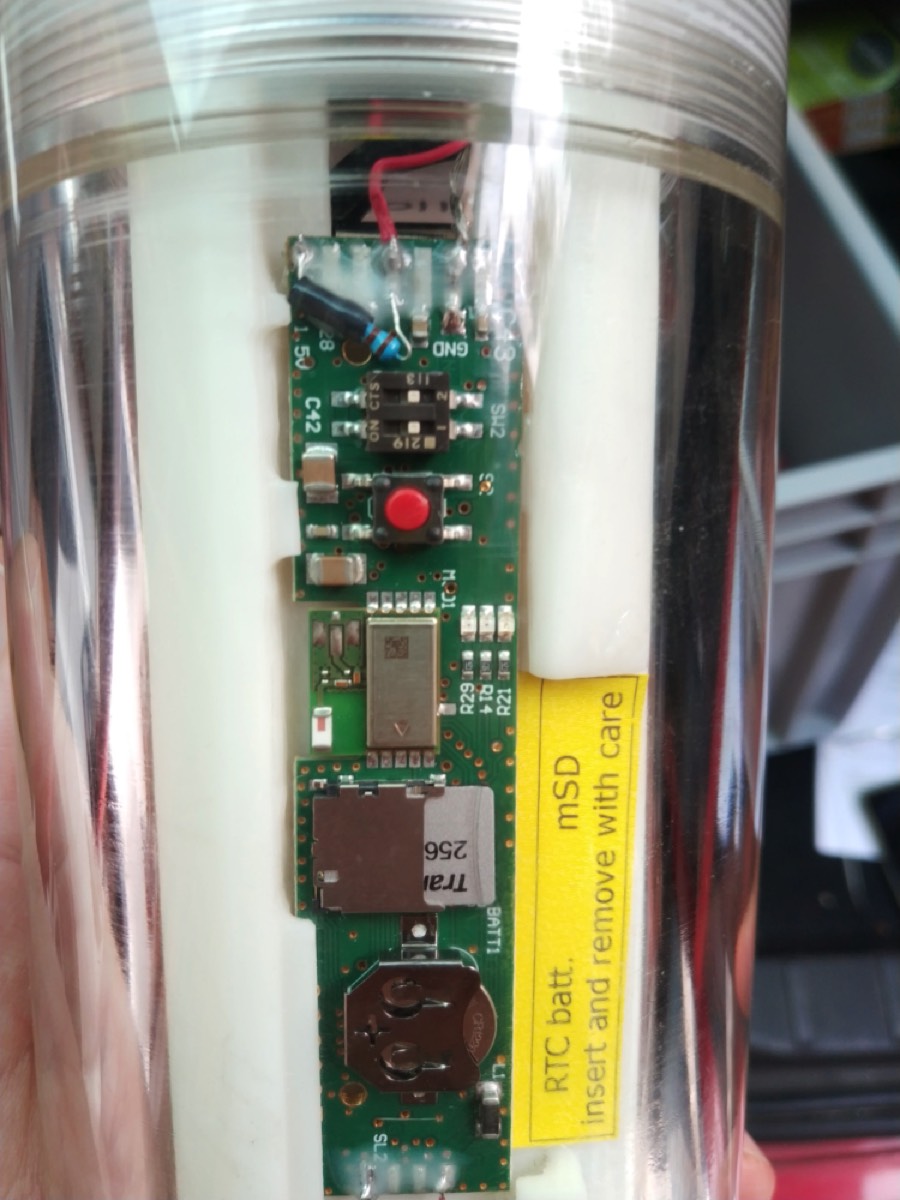
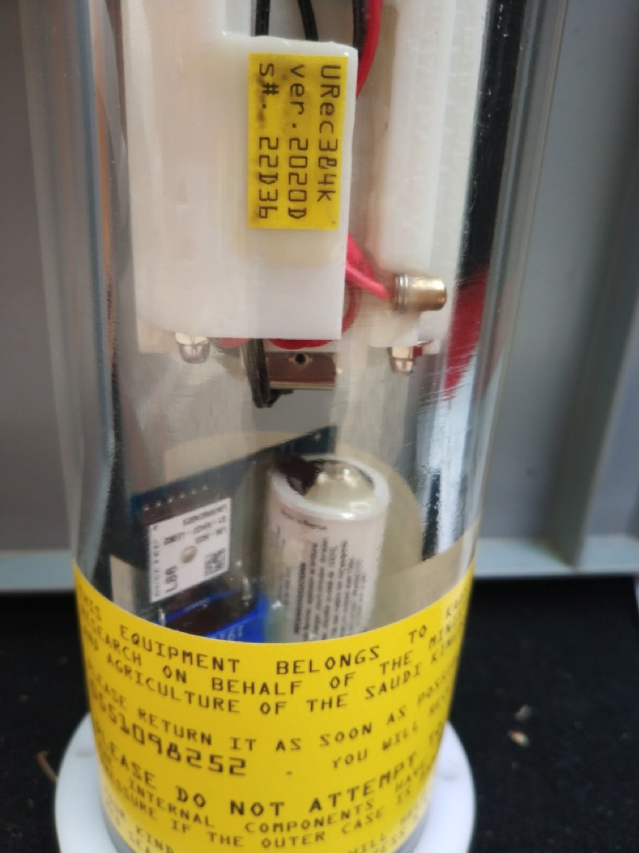
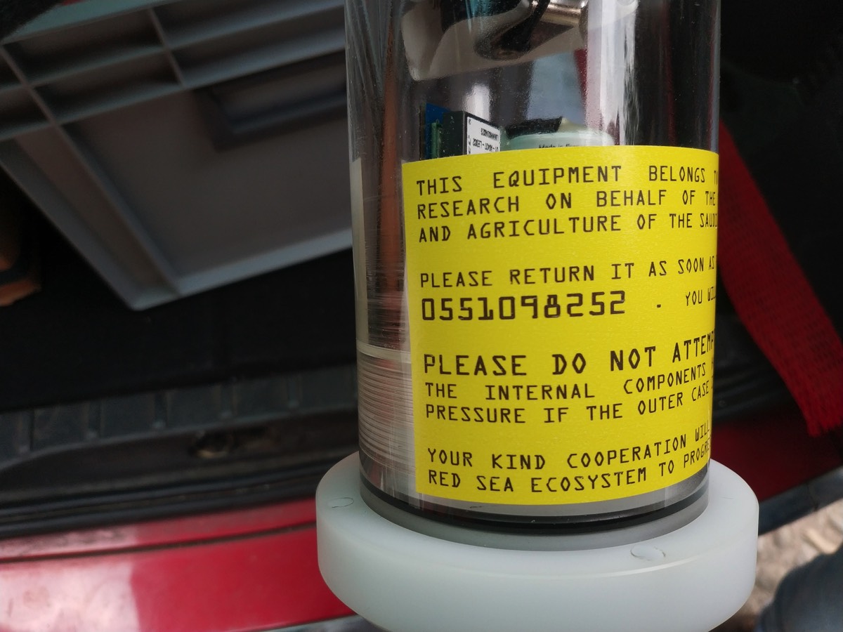
Manual of the uRec384k 22D units
The battery life estimator is in this XLS file
A screen capture of the programming sequence on your android device
Sampling rate: use 192kHz
Frequency response of the recorder: 10Hz to about 90kHz
Gain: use 1x (NO GAIN)
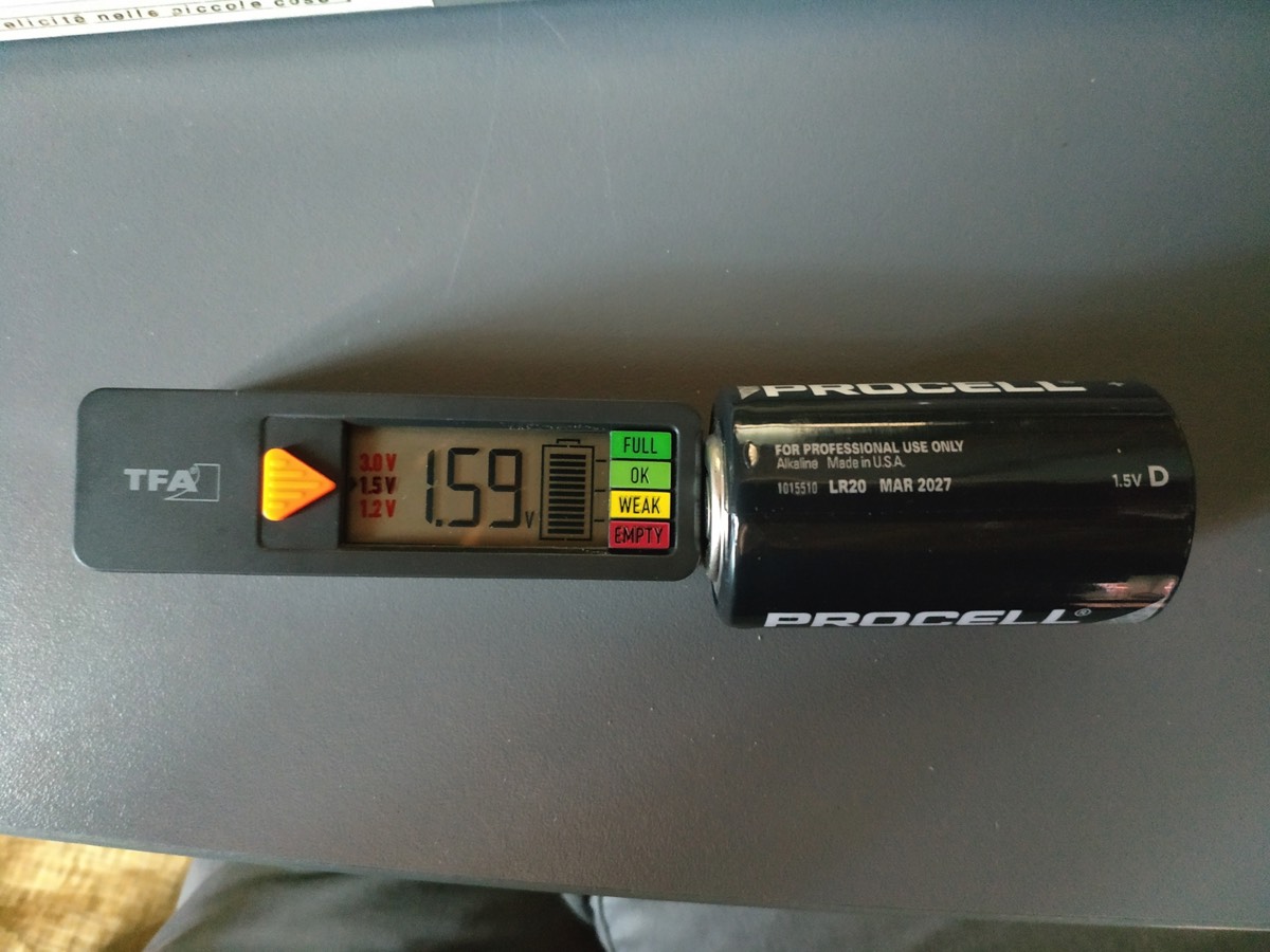
Power supply: USE 3x SIZE D cells, alcaline batteries. Change batteries when below 1,2V (WEAK indicator on the battery tester)
Memory: use the provided 256GB mSD card
Real-time clock: used to timestamp the recorded files. Please sync with the programming device.
Hydrophone: Sensor Technology SQ26-05
Frequency response of the recorder: 10Hz to about 90kHz
Gain: use 1x (NO GAIN)
Power supply: USE 3x SIZE D cells, alcaline batteries. Change batteries when below 1,2V (WEAK indicator on the battery tester)
Memory: use the provided 256GB mSD card
Real-time clock: used to timestamp the recorded files. Please sync with the programming device.
Hydrophone: Sensor Technology SQ26-05
GPS bottom caps are always ON.
Positions are sent, as default, once a day per each unit.
Here you find the matching numbers of the GPS with the serial of the recorder, just to match our records: https://docs.google.com/spreadsheets/d/15VcZCLVs1eZOAzrD-ZhnZFO7kAoun1RxYTn5UJwRUuo/edit?usp=sharing
to access the position of the unit we have set up an account devoted to your case:
from a computer you should go to https://app.cphtrackers.com/en with your browser,
login is urec.sa@nauta-rcs.it
password is YET.found2
from your mobile android device you should install
CPH Trackers from Play Store
logging in with the same credentials.
Trackers are always ON and are currently sending one position every 24hrs when satellites are in view and they are out of the water.
They will be good for receiving a ping if the units are stolen and kept onboard.
They are configured to work on the SA mobile networks, and not only.
Please put them in the view of the sky so that they can sync and remember their working area for the first time.
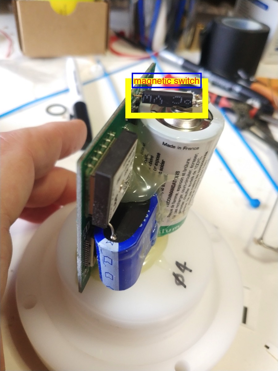
There is a magnetic switch on the top of the battery, as shown in the picture. If you place a small magnet (provided with the main shipment) on the black bar, the unit will be switched off. This is good for long-term storage.
They will be good for receiving a ping if the units are stolen and kept onboard.
They are configured to work on the SA mobile networks, and not only.
Please put them in the view of the sky so that they can sync and remember their working area for the first time.
There is a magnetic switch on the top of the battery, as shown in the picture. If you place a small magnet (provided with the main shipment) on the black bar, the unit will be switched off. This is good for long-term storage.
Programming the acoustic sampling
Sequence
Open the canister unscrewing the cap with the hydrophone.
Do NOT open the bottom end with GPS transponders unless necessary.
Do NOT open the bottom end with GPS transponders unless necessary.
If batteries are known to be good (based on previous experience and a battery life data record and/or the battery life estimator) you can restart and reprogram using the provided big magnet from outside the canister. Place it near the golden metal spot near the serial number label and the unit will be hard-powered-OFF.
When removing the magnet you will see the blinking lens and you will be able to reprogram the unit as described below without opening the unit.
When removing the magnet you will see the blinking lens and you will be able to reprogram the unit as described below without opening the unit.
Check the batteries and change them if WEAK when tested with the provided battery tester.
ALWAYS PROGRAM A NEW SAMPLING PERIOD FROM SCRATCH WHEN REMOVING THE BATTERIES or when you turn the unit OFF with the magnet.
THIS IS THE SAFEST WAY TO GO!!
THIS IS THE SAFEST WAY TO GO!!
- LAUNCH THE UM384BLE app on your android device.
- tap on CONNECT TO MIC
- tap on SCAN & CONNECT
- place the batteries in the uRec unit
- see if it is connected
- tap on TIMING
- select MODE REPEAT
- confirm with OK
- tap on ADD TIME
- tap on SET FOR NOW if the sampling is to be started immediately, or SET DATE AND TIME if the sampling must be started at a later time. PLEASE MAKE SURE THAT THE START TIME IS IN THE FUTURE. IF THE SAMPLING START IS IN THE PAST NO RECORDING WILL BE MADE and the recording cycle will not start.
- select the duration of the recording (12 hrs = 12:00)
- select the duration of the pause (1 min = 00:01)
- the two suggested sampling periods are 00:10 of recording and 00:05 of pause; 00:15 of recording and 00:05 of pause.
- select SAMPLING RATE at 192kHz
- skip the TRIGGER tab
- on the OTHER tab write the DEVICE NAME according to the serial number of the unit (22Dxx)
- let the File Split Size in Min (minutes)
- File Size in minutes can be set at 15 minutes
- Confirm and go to CONNECT tab
- press SEND TIME
- press SEND CONFIG. button
- wait for the program to be transferred correctly.
- you will see the unit restarting with blinking led and it will then start the programmed sequence according to your instructions.
REPAIR
FIRST POSSIBILITY:
let's change the broken component only. In the delivered pack you find a small plastic bag with a small circuit with 3 wires soldered. The three wires are ONE BLACK, ONE RED LARGE, ONE RED THIN.
you can simply cut and remove the Broken identical circuit on the underwater recorder, using a small blade, screw driver or whatever. Then CUT the three wires from the broken component, and simply connect the new component: BLACK to BLACK, RED large to RED large, RED thin to RED thin.
Use some hot glue, or tape to keep the new component in position.
It is that easy.
SECOND OPTION:
REPLACE THE WHOLE SHELL and reconnect the existing hydrophone
FIRST release the existing shell from the cap. DO this by unscrewing the NUTS at the bottom. Nuts are kept in position with some resin. simply broke it and unscrew.
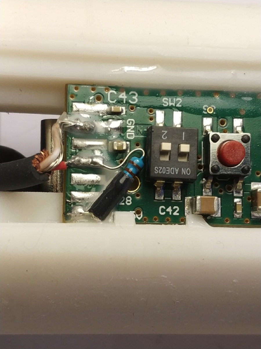
Once that the back shell is free to move slide it out and CUT the wires from the hydrophone as near to the board as possible.
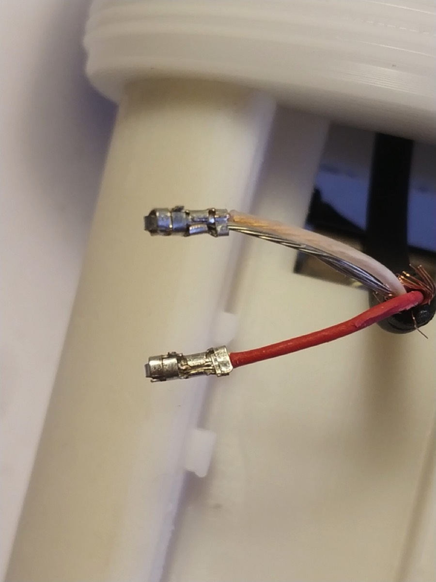
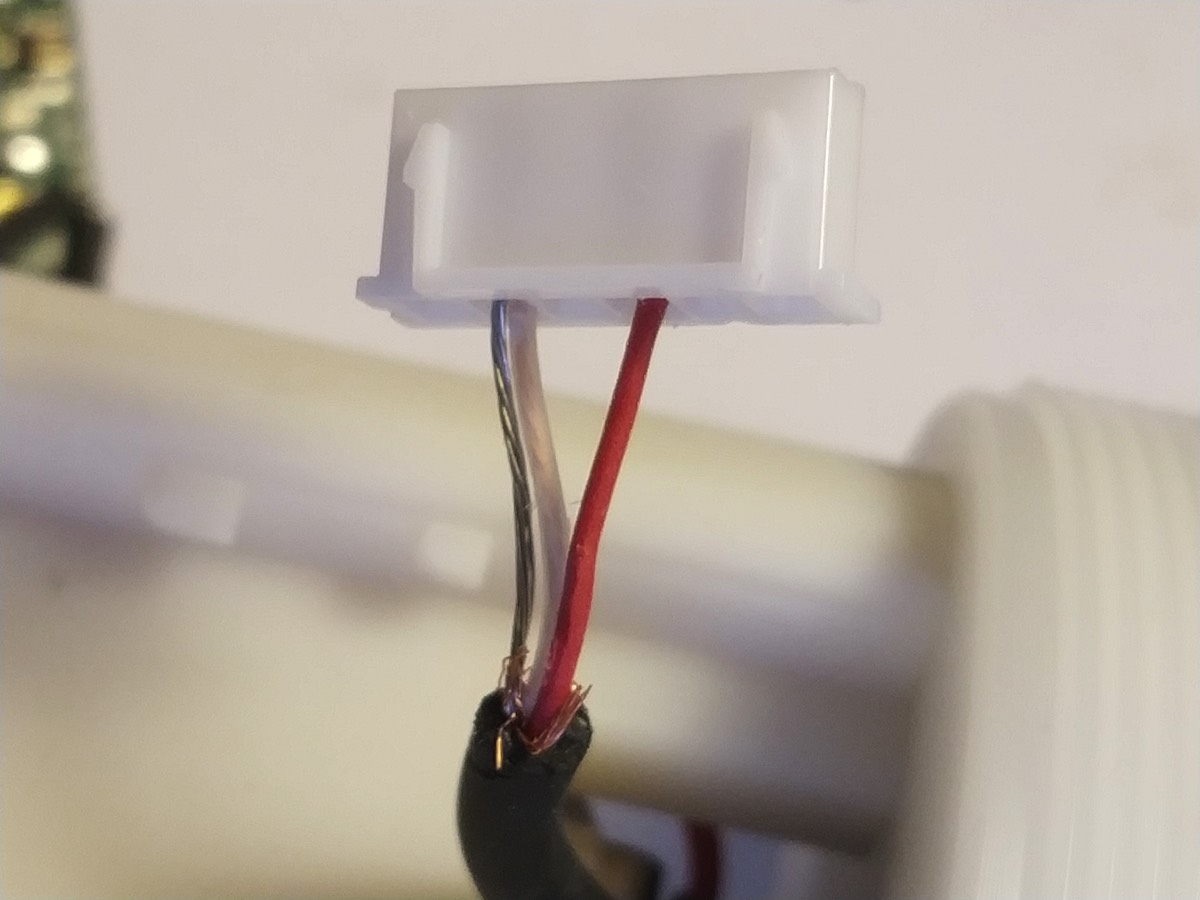
The hydrophone has THREE WIRES: SHIELD (the metal around the wires and its shorted straight wire interconnected), RED and WHITE.
RED IS THE SIGNAL CABLE
WHITE AND SHIELD MUST GO TOGETHER.
The new back shell you have received has connectors (while the existing shell does NOT have connectors). YOU MUST CONNECT THE WIRES FROM THE HYDROPHONE TO THE PROVIDED CONNECTOR (in a small plastic bag), and then connect the hydrophone to the board via the connector.
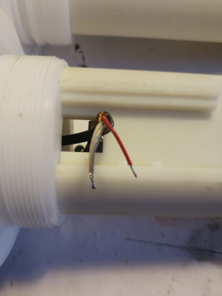
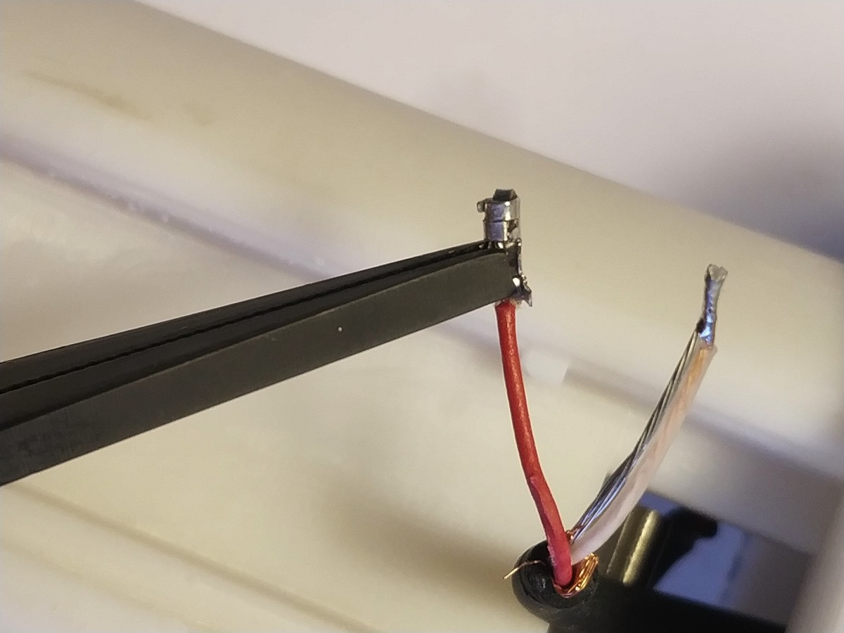
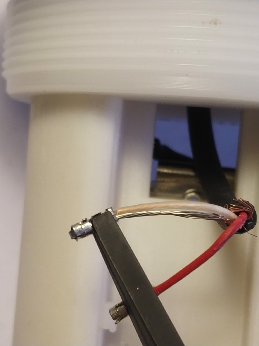
So the sequence is: USE THE PROVIDED METAL PINs (there are several, you need two) and connect one metal pin to red wire and another to the WHITE&SHIELD. Use the pliers to gently connect wires to the pins.
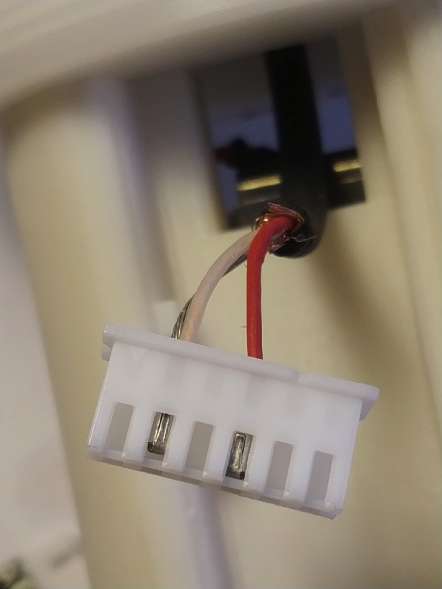
Once connected you must insert the pins into the white plastic shell.
CORRECT POSITION IS CRUCIAL.
Looking at the board, positions are 6 from left to right.
RED WIRE MUST GO TO PIN 3
WHITE/shield MUST GO TO PIN 5
pins 1,2,4,6 are empty.
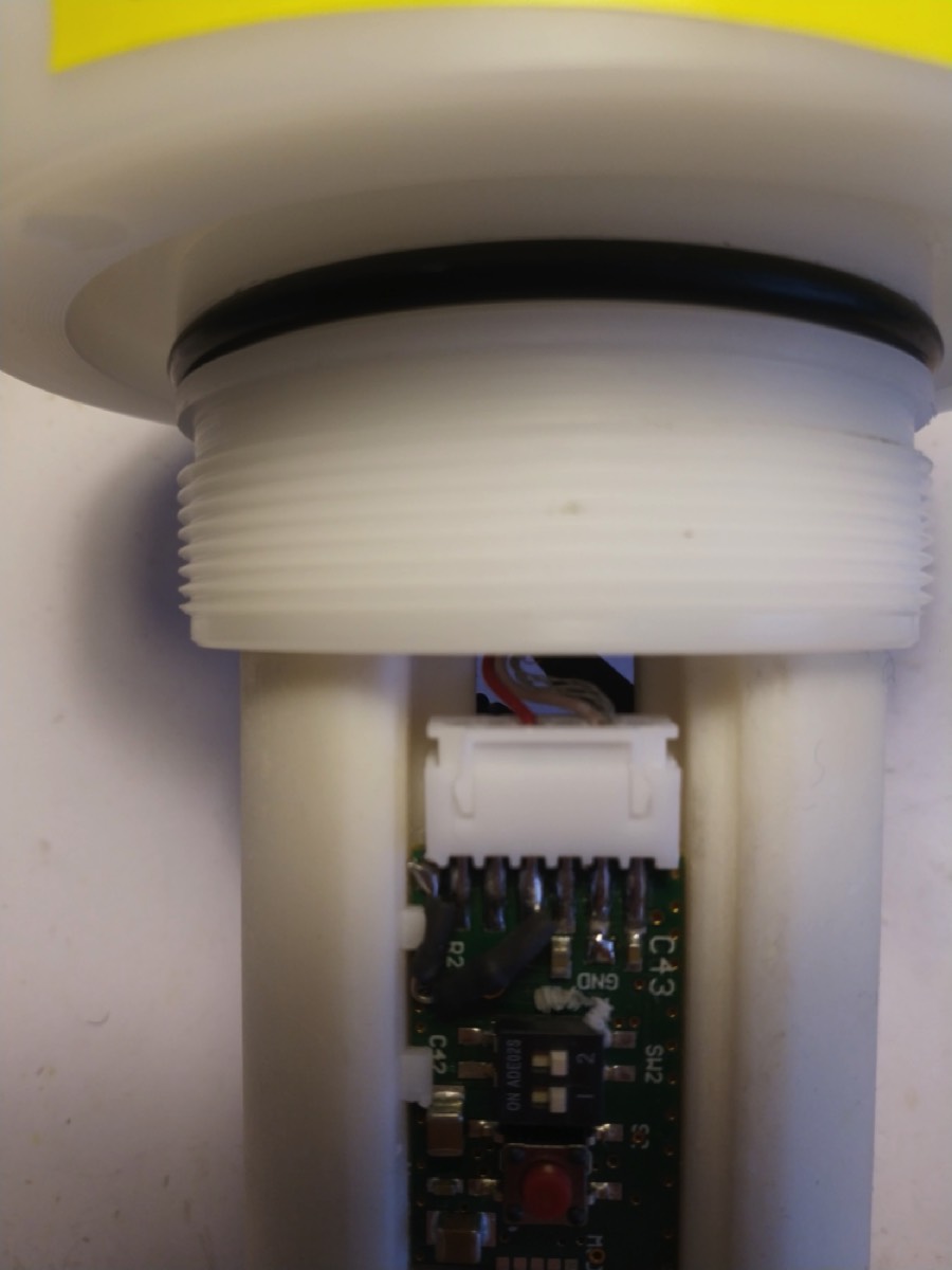
Connect the mating connectors.
All the rest is already connected.
You can check launching UM384BLE application
connect to the repaired board as usual
CONNECT TO MIC
SCAN&CONNECT
once connected tap on AUDIO LEVEL (bottom left)
If the connection is correct you will see spikes when tapping over the hydrophone.
REPLACE THE WHOLE SHELL and reconnect the existing hydrophone
FIRST release the existing shell from the cap. DO this by unscrewing the NUTS at the bottom. Nuts are kept in position with some resin. simply broke it and unscrew.
Once that the back shell is free to move slide it out and CUT the wires from the hydrophone as near to the board as possible.
The hydrophone has THREE WIRES: SHIELD (the metal around the wires and its shorted straight wire interconnected), RED and WHITE.
RED IS THE SIGNAL CABLE
WHITE AND SHIELD MUST GO TOGETHER.
The new back shell you have received has connectors (while the existing shell does NOT have connectors). YOU MUST CONNECT THE WIRES FROM THE HYDROPHONE TO THE PROVIDED CONNECTOR (in a small plastic bag), and then connect the hydrophone to the board via the connector.
So the sequence is: USE THE PROVIDED METAL PINs (there are several, you need two) and connect one metal pin to red wire and another to the WHITE&SHIELD. Use the pliers to gently connect wires to the pins.
Once connected you must insert the pins into the white plastic shell.
CORRECT POSITION IS CRUCIAL.
Looking at the board, positions are 6 from left to right.
RED WIRE MUST GO TO PIN 3
WHITE/shield MUST GO TO PIN 5
pins 1,2,4,6 are empty.
Connect the mating connectors.
All the rest is already connected.
You can check launching UM384BLE application
connect to the repaired board as usual
CONNECT TO MIC
SCAN&CONNECT
once connected tap on AUDIO LEVEL (bottom left)
If the connection is correct you will see spikes when tapping over the hydrophone.