
RASPtimer gen. 2
How to prepare your m-audio microtrack 24/96 for the RASPtimer
Designed to fit the m-audio microtrack recorder, the RASP timer is a programmable circuit board that mimics the keypress of the standard keyboard of this recorder.
Two buttons are emulated: ON/OFF and RECORD.
A rather simple modification of the recorder is required to use this timer.
This modification is explained here.
It goes without saying that the described operation is done at your own risk, and voids the warranty of your equipment. The following description is for your reference only. Seek help form a skilled person if you need.
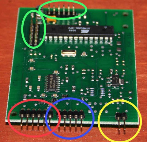
The RASP timer has five ports, and its size fits the back of a microtrack recorder.
The YELLOW port is for POWER, and accepts up to 5.5VDC. This is the general powering for the whole system , including the recorder.
The BLUE port is for the serial interface (standard RS-232). It goes to the computer that programs the interface via the configuration software.
The RED port goes to the recorder. Six pins are used: two for the power, two for the ON/OFF switch, two for the RECORD button.
The green ports are for firmware updating and expansion bus, and are not normally used.
As the internal battery of the recorder will be removed, you must consider that once modified you microtrack recorder will always require external powering, NOT VIA THE USB PORT (it does not work if a battery is not connected). This powering could be provided using the new connector, even without the RASPtimer board installed.
Removing powering will cancel the time/date information, while the recording settings will in general be retained.
The software offers:
cyclic recording and scheduled recording, with up to 24 user-defined periods of recording in a day
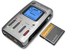
The microtrack
preparing the m-audio microtrack
As stated, the RASPtimer acts as a keypress on the recorder, doing as you are there when you are not. Normally four wires have to be soldered to the recorder in order to have it ready to fit the RASPtimer. The four wires are those related to the ON/OFF switch, the RECORD button, the BATTERY contacts. The standard battery in the recorder has to be removed, and external power feed has to be provided. In our tests, and during development, we used four NiMH 1,2VDC recharcheable batteries with excellent results. This "battery change" is needed as the standard power feed via USB port triggers the recorder ON all the time, and results in a continous ~250mA power consumption.
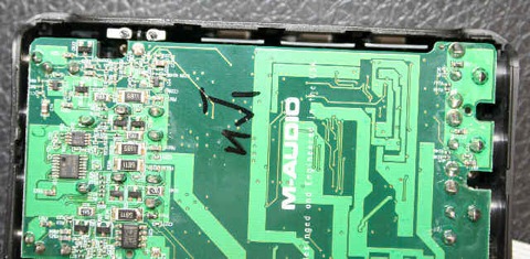
In order to prepare the unit, first you have to remove the back cover. It is a painful operation, that may result in some cracks on the retaining pins. The manufacturer decided not to put any screw on he back , so the cover is just a snap-in plastic shell. Starting from the corners, and with no fear, using a sharp cutter blade, try to divaricate the black plastic from the silver one. It takes a while, but at the end you will open it.
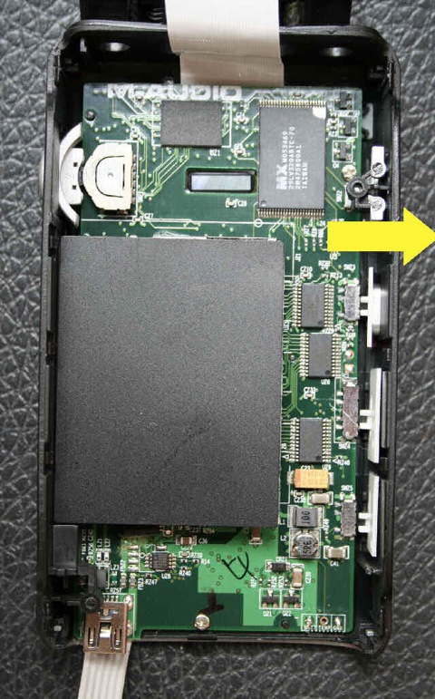
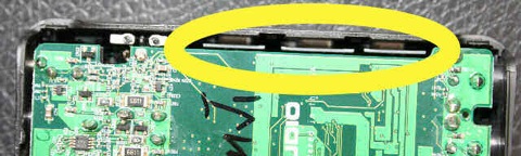
The first thing you will see once opened is the big and flat battery. It is exactly stuck where the M-AUDIO print is on the picture on the left.
You must remove it. Cut the wires, place some tape on them and store the battery in a plastic bag somewhere in a safe place.
Two screws keep the first circuit board in place. There are four screws in total, two long and two short. The two long ones are those of the first board.
Unscrew these two screws and gently take the first board off. A white contact strip connects the two boards. Do not stress it and leave it connected.
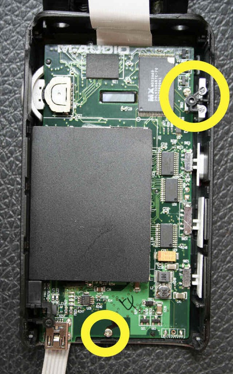
Two more screws are here, and they must be removed.
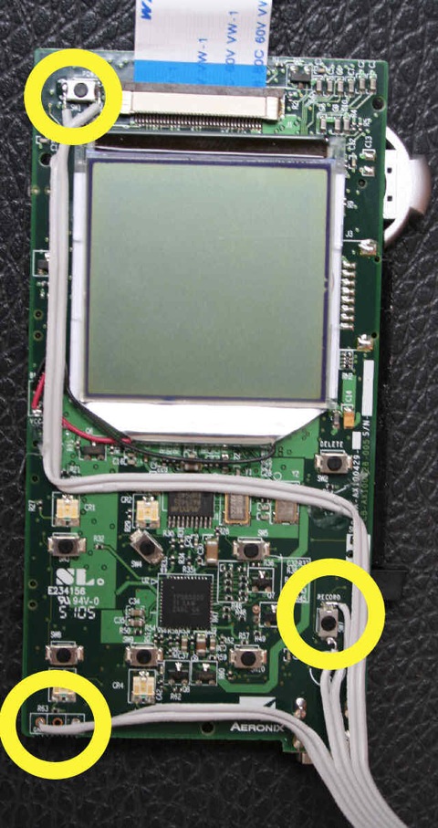
Now the 2nd board is out and free. It is time to solder the six wires.
It is not an easy task unless you are somehow experienced. You should fatten a bit the current soldering, wet the wires with the solder wire, and using a SMALL & GOOD soldering iron set the wires in position. Seek help if you need it.
You can use a strip-cable, like in the picture, or anything you feel confident with. Sticking to the good habit of taking all needed contacts out, you will need six wires, even if two take the same ground signal.
Pins 2 and 6 (hereafter) are common ground and could be connected together to a different ground (this up to hardware version delivered in december 2006)
Microtrack 24/96:
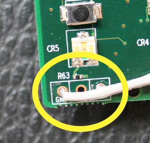
MODU 6pin FEMALE, gold pins: 1: POWER switch (on the picture above this is the very first soldering at the top-left) 2: GND for power switch (please double check THIS IS GROUND; with current hardware you can also leave disconected as ground is replicated on pin6. This is the top-right soldering) 3: RECORD SWITCH 4: RECORD SWITCH 5: +4.7VDC BATTERY (BATTERY is indicated on the PCB) 6: GND for BATTERY (GND is indicated)power switch is replicated shortening pin 1-2 (1..2 second period) or grounding PIN 1
RECORD button is replicated shortening pin 3 and 4
PIN 5 is for positive power feed (do not exceed +5.5VDC referred to common ground)
Three are available (but the TEMP pin is unconnected. Leave it as is).
Check the solderings, carefully reassemble the 2nd board (CAREFULLY !! it is easy to spoil the microswitches on the right side).
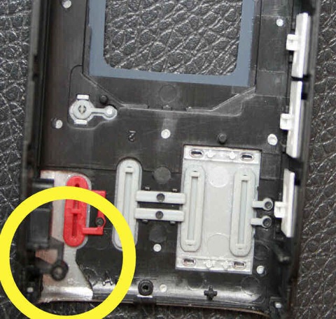
The first board is now still out. As it goes in together with the bottom mask (the plastic that carries the L-R line outs, S/PDIF markings) you must cut that plastic mask right over the USB port (just the upper right corner) to have the cable out without being pinched.
Right before putting the first board in, check that the three sliders (hold, mic level and phantom power) do engage their relative switches.
Screw the first board in.
You have done it.
You must now make sure the wires are correctly connected (correct sequence) as stated in the RASP tech sheets also.
Use a standard 6-pin MODU connector (or anything you like with correct 2.54mm spacing) to terminate the cable.